Today I�m going to talk about another Blender Script. This Script is called Geom Tool and his primary function is to aid in the modeling process, adding more tools and functionalities that doesn�t exist in Blender.
This Script was developed by a user called Guillaume �GuieA_7� Englert. You can download the Script file here:
http://www.hybird.org/~guiea_7/
I think this tool is very useful, mostly when we apply it in more geometric modeling. Like when we have to model Scenarios and Furniture for architectural visualization.
I hope this tutorial can help anyone interested in use this tool and of course aid my students that will begin to study Blender.
Before anything is important to say that I�m going to use Blender 2.42a and Geom Tool 0.3. After you have downloaded the Geom Tool, you must extract the two files that are inside the zip file. Place the file named �mesh_geom_tool_math.py�, inside the folder called �bpymodules� that is located in the Blender Scripts folder. Then place de file called �mesh_geom_tool.py�, inside the Blender Scripts Folder.
After you have placed the Geom Tool files in their respective folders, we can use the Script. Use the Mesh menu, when you edit some object for to access the Geom Tool Script. See how we can access the option in the Mesh menu on Image 01.

Image 01
When we click in the Geom Tool option the script menu, with all his options, will popup like the Image 02 show�s.

Image 02
Let�s see what every one of his functions does, but before we start it�s already possible to see that his primary functions are project, intersect, align and distribute elements. The Script manipulates vertices, edges and faces with this functions.
Something important about this Script is that the order you use to select vertices, edges and faces don�t matter, you can use any order you want.
Project:vert(s)->face
This option projects vertices over a face. You can select the face and vertices in any order. After you have selected the objects access the Geom Tool in the Mesh menu, and the vertices will be projected over the selected face (Image 03). You must be careful with the number of vertices, because more then three vertices will be interpreted by the script as a face and you will get an error message.

Image 03
Project:vert(s)->face(copy)
This option does exactly the same thing the previous option. The difference is that the selected vertices are just copied over the face and not moved. This way you still have your original vertices in their original place.
Project:vert(s)->edge
With this option the selected vertices are moved over an edge. See how it�s possible to project the selected vertices in Image 04, this way the vertices will be placed exactly over an edge.

Image 04
Project:vert(s)->edge(copy)
Here we have the same function, but the vertices are not moved. Instead the selected vertices are copied for the projected place over the selected edge.
Intersect: face/edges(s)
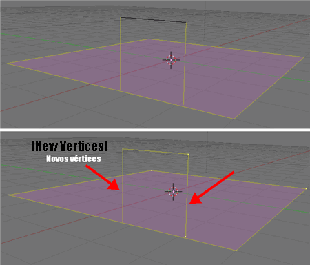
This option creates an intersection between a face and selected edges. With the intersection, new vertices are created in the exactly place where the face and the edges �touch� each other. See the result in Image 05.

Image 05
Intersect: face/edges(s) (cut)
Here we have the same operation, but the edges are modified. In the place where the intersection happen the edge is splitted, and new vertices are added to the edge. In the final result we have a segmented edge.
Intersect: face/face(s)
This option looks a lot like the Boolean modifier in Blender. But there is a difference, the modifier requires two different objects and here you can apply the intersect with just one object. The result is showed in Image 06.

Image 06
The intersection is represented by the creation of new edges.
Intersect: face/face(s) (cut)
Here we have the same operation, but the intersection is showed directly over the faces.
Nearest plane: verts
With this option is possible to project vertices over the nearest plane (face). Select the vertices you want to project and choose this option.
align: verts
In this option the selected vertices are aligned over an axis. See Image 07 for an example.

Image 07
distribute & align: verts
Here we can align the selected vertices over an axis and distribute them with a regular measurement.
distribute: verts
With this option we can only distribute the selected vertices over the same axis with a regular measurement.
Well, I hope this article can be useful to anyone interested in learning how to use this great Script. In the near future i will translate more of my tutorials!
And sorry for any mistakes in my English! 🙂